A number of years ago I was discussing with another researcher the concept of dial-a-yield (DAY) weapons (variable yield weapons) using “doors” between the primary and secondary stage to control yield. The basic idea being that when closed, no x-rays can flow to the secondary and therefore no secondary yield is produced.

Figure 1 — Tetraethyl lead molecule. Source: https://en.wikipedia.org/wiki/File:Tetraethyllead-3D-balls.png
At the time I had been looking into leaded fuel, octane ratings and tetraethyl lead (TEL). TEL is a neurotoxic organolead compound that was once used to increase the octane rating of fuels before being phased out due to its incompatibility with now mandatory catalytic converters. It was eventually banned from sale for use in road vehicles almost everywhere due to its toxicity, but remains in use as an octane booster in avgas for piston aircraft.
With that topic on my mind, I threw out an idea: Instead of using mechanical doors with lots of moving parts, why not just use a liquid that contains high-Z elements — such as TEL — and pump it to your interstage to act as the door?
The response I got back was to the effect of: if you are looking at a liquid system, why not use mercury?
It was also pointed out that elemental mercury is actually less poisonous than TEL. But hold that line of thought, because once we get to it, we’ll be adding thallium to the mix.
Some basic principles
To cover the topic in a brief a manner as possible, in a two-stage nuclear weapon there are three areas where you can control nuclear yield: in the primary stage, in the secondary stage, and in the interstage region — which is to say by changing how much energy moves from the primary to the secondary and the timing of that energy.
Obviously, in a single-stage device only the primary yield control methods are available to a weapons designer, and in a three-stage weapon, additional locations to control yield are available. I will summarise the various methods I can think of below. This is probably not an exhaustive list.
Primary yield control
There are three ways this can be done: by changing the amount of deuterium-tritium fusion boosting, by changing the timing of neutron initiation, and by changing the maximum criticality reached by the primary.
The first is self-explanatory — though I am skeptical of suggestions found online that the amount of boost gas is varied over some wide range to precisely control yield as it’s not really feasible to rapidly and accurately measure out small amounts of gasses in a compact package. For example, in a production environment, they used slow calorimetry methods to measure boost gas bottle amounts.[1] Therefore, it is likely an all boost gas or no boost gas system that is used. Any weapons that do have more than two primary yield options I expect are using multiple boost gas bottles. See my post Some Details on the W62, XW63, XW65 and W70 Warheads for a known example of this.
Controlling neutron initiation timing is another suggestion commonly thrown about, but I am going to argue that it is just not used. It’s simply too unpredictable and could easily be thrown off by outside neutron sources such as from other nuclear detonations. Imagine if in some tactical environment a planner has calculated that three 5kt detonations in close pattern are needed to destroy an enemy formation without risking friendly troops, and the planner only has higher yield DAY weapons available to them, so higher yield weapons set to 5 kt are used. But, because the system is using neutron timing to control yield, additional stray neutrons from delayed fission from the first device cause the second and third weapons to go off at full yield. Such a yield control mechanism is too risky, especially given that more reliable methods of yield control exist.
The last option of changing the maximum criticality (K) of the system could be achieved through two means. The first is by simply changing how much material is in the pit. The W33 8” nuclear artillery shell is an example of this as it was possible to remove HEU rings and replace them with Du rings to reduce yield. The second would be by carefully mistiming the implosion system of an implosion device. I am slightly skeptical of this being used as it seems like it would require lots of nuclear tests to get right and due to there simply being better ways of controlling yield, but I am not going to write-off the whole concept either. It might have had a place in small unboosted weapons such as a nuclear artillery shells.
Secondary yield control
In the secondary, yield control likely focuses on the spark plug.
The spark plug provides the initial heating once the secondary has been compressed to fusion densities. Without it, the fusion fuel needs to rely on self-heating reach fusion temperatures and will self-disassemble (i.e. explode) before the maximum amount of fusion has taken place. Spark plugs come in two varieties: fission spark plugs like those used in most conventional thermonuclear weapons, and fusion or gas spark plugs consisting of deuterium-tritium gas which are believed to be used in some very advanced designs like Ripple[2] and in enhanced radiation weapons like the W66, W70 Mod 3 and W79.[3]
In secondaries using fission spark plugs, the systems probably insert or remove a neutron poison from the spark plug. It may also be possible in some designs to remove the spark plug altogether. It’s not clear if either system has ever been used, but given it seems simple and reliable in concept, I expect it has at least been explored.
Gas spark plugs are similar in operation to boosted primary systems, and carry the same limitations of metering out small quantities of gas.
Interstage yield control
In the interest of staying on topic, I am going to just state that the interstage of a nuclear weapon is the device that modulates x-ray flow from the primary to create a more ideal x-ray pulse shape for efficient compression of the secondary stage, and not elaborate any further. Jon Grams’ Ripple paper[2] discusses this topic, and the concept of changing the shape of the x-ray pulse is used in various inertial confinement fusion schemes.[4][5]
In an interstage yield control device, the system would either completely block the x-ray flow to the secondary so that it produces no yield, or it would partially or fully disable the x-ray modulation component so that the secondary is compressed less efficiently and therefore less yield is produced.
The aforementioned doors or shutters is one method suggested. The design would consist of a panel made from high-Z material that is closed when you want to block x-ray flow, and opened when you want x-rays to flow. The shutter would be actuated with some mechanism such as a small electric or pneumatic motor, or by an explosive squib. The only issue I see with this concept is space: when opened the shutter needs to go somewhere, it needs free space to open and close through and this space may need to be filled with a channel filler (a foam). None of these are difficult to overcome, but in the very small volumes that we know canned secondary assemblies (CSAs) can have, it’s not clear where all the parts might go. This is where I threw around the idea of a liquid shutter.
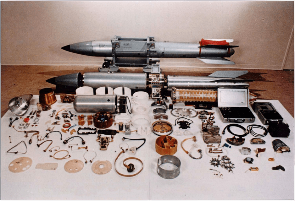
Figure 2 — Disassembled B61 bomb. The bright silver cylinder centre-left is probably the CSA. Source: https://commons.wikimedia.org/wiki/File:B-61_bomb_(DOE).jpg
Liquid metal
With this idea in mind, I went looking.
The first piece of evidence was found on OpenNet, titled “Interview Notes Taken by S. Flack on November 6, 1996”.[6] The document is described as “never classified” in the description, but it has clearly been heavily redacted and on page five a secret marking can be seen crossed out. The interview notes (which are out of order) discuss one production process at Oak Ridge that used mercury-thallium alloy and possible environmental leaks from the process. A cursory search of OpenNet reveals many documents associated with Susan Flack and it appears that she was involved in documenting historical use of mercury and other hazardous materials at Oak Ridge.
Starting with page four we have what looks like a scan from another unknown report with notes scribbled below. The scan makes it clear that the process that uses mercury-thallium alloy was not related to lithium-6 separation, that it was used in a weapon component and that the quantities used were small compared to Li-6 separation (Li-6 separation at Oak Ridge between 1950 and 1963 required an mercury inventory of 11,000,000 kg of which approximately 3% was lost[7]). The notes are the sort of thing many researchers would write down to indicate something that should be looked at further. The bottom of the page is cut off, but the word “dismantlement” can clearly be seen.
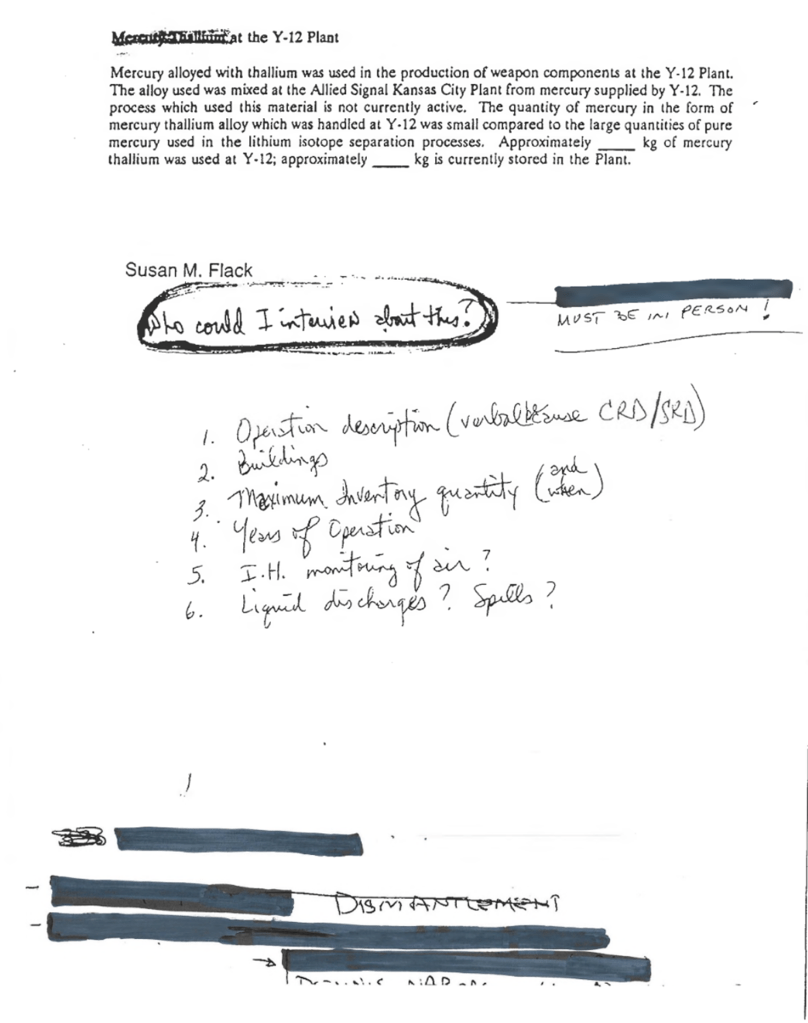
Figure 3 — Page 4 of “Interview Notes Taken by S. Flack on November 6, 1996”.
On page 2, is says Hg-Th amalgam. Given the document talks of thallium, I will assume that this is a typo and the author is not referring to mercury-thorium amalgam.
It goes on to say that it was a closed system in a fume hood hooked to a stack i.e. a fume vent to atmosphere. But it then goes on to discuss 10 cc (10 ml) test vials being filled and left over material being poured into 75 lb mercury bottles, which clearly indicates that it was not a closed system. “9720-18” is mentioned, which is a naming convention used at Oak Ridge for buildings, as is “B-4”.
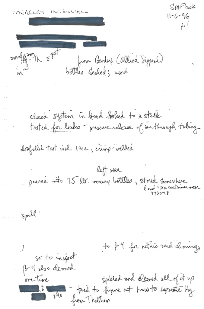
Figure 4 — Page 2 of “Interview Notes Taken by S. Flack on November 6, 1996”.
Page 3 is heavily redacted, but does list three buildings: 9204-2E, 9204-4 and 9720-18.
Building 9204-2E is described as being for “radiography, assembly and disassembly, quality evaluation, and production certification for nuclear weapons secondaries”.[8, p. iv] i.e. it is where final assembly of canned secondary assemblies takes place and is therefore central to the construction of US thermonuclear weapons.
Building 9204-4 dates from the Manhattan Project era and was initially built to house two beta calutrons for uranium enrichment. For that reason, it was also known as Beta-4 or B-4. The process was discontinued in 1946. From 1953 to 1957, the building was used for the electro-exchange (ELEX) lithium enrichment process which used mercury, and in the 1960s and 1970s it was reconfigured to support weapon fabrication and support operations.[9] An unclassified history of the building can be found here.[10]
Building 9720-18 is described as a warehouse.[8, p. 27]
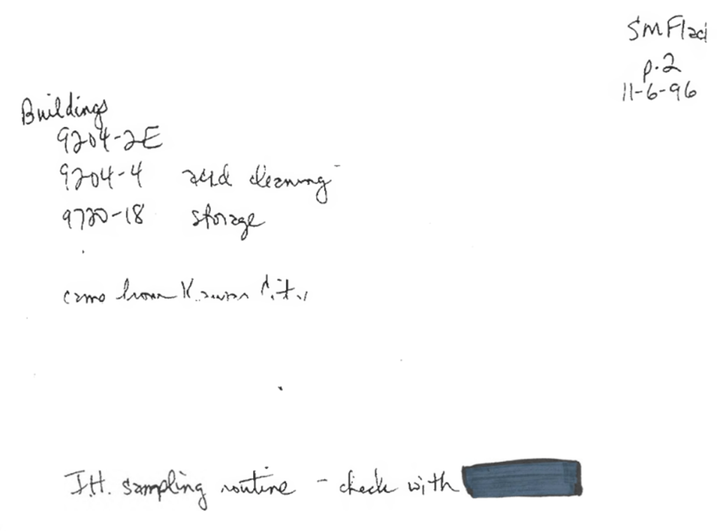
Figure 5 — Page 3 of “Interview Notes Taken by S. Flack on November 6, 1996”.
One page 5 some partially redacted calculations are given, with the heading “Hg-Thallium Release calculations”. I will address these first before looking at the rest of page.
It states a 30 lb alloy bottle, a redacted amount of units produced, then has another line for “lbs alloy”, then redacted percentage of “alloy used per unit”, for a redacted pounds total alloy. It then states, “x .08 % Hg in alloy”, for a total of 32.2 lb of mercury.
There are a few issues here, the first of which is that above 90% thallium, Hg-Tl alloy has a melting point above 300 °C,[8] but they are referring to liquid metal in all instances in this document. Therefore, they cannot be referring to 8% (or 0.08%) mercury alloy. It seems clear that the mercury and thallium ratios have been mixed up here, as 8% thallium in mercury produces an alloy with a freezing point of approximately -60 °C, significantly lower than the -38.83 °C of pure mercury.
If this redacted calculation has assumed 8% mercury content, this puts the total of 32.2 lb of mercury total in doubt. But with some simple maths we can back calculate to find that the total alloy amount as 402.5 lb if 8% thallium is used, and 40,250 lb if 0.08% thallium is used.
But even then, I find the calculations suspect. Logically, if you wanted to calculate the total mercury consumption of this classified part, you would take the number of units, multiply by the amount alloy needed per unit (which I assume is what “[redacted] lb alloy” on line two of the calculation is) to get a total alloy amount, then multiply by the mercury percentage to get a total mercury amount. But in the middle of this calculation is “% of alloy used per unit”, which sounds like an attempt to calculate the amount of alloy needed per unit, from a known total number of units and total alloy amount.
The notes at the bottom of the page mostly rehashed what has already been mentioned. It mentions a closed system, but it’s also not really closed. Unused alloy was returned to 70lb bottles. The alloy was also cleaned in Beta-4 using nitric acid, and that someone was investigating separating thallium and mercury.
Figure 6 — Page 5 of “Interview Notes Taken by S. Flack on November 6, 1996”
Leaky Secondaries
I made little headway investigating this for more than a year until I stumbled on the Defense Nuclear Facilities Safety Board’s weekly reports on the Pantex Plant. The reports usually consist of a one-page summary of various safety related matters that the DNFSB resident inspectors had witnessed during the previous week.
The report for week ending 13th February 1998[9] states that a technician found mercury contamination on the inlet of a gas sampling machine used to obtain internal weapon atmosphere samples. The total amount of mercury was about 1 teaspoon. Assuming 1 teaspoon is about 5ml, this is approximately 70g of mercury that leaked out of the device.
It’s not specified what they mean by gas sampling of internal atmospheres. This could be for example gas sampling the whole weapon to detect tritium leaks, or it could mean sampling of a secondary to detect aging related degradation.
Looking through the resident inspector reports from 1997 to 13th February 1998, I believe that this weapon was a W69 warhead as the W69 was the only major dismantlement program running at the time. W69 dismantlement began late June 1997.[10] B61-5 dismantlement concluded in mid-August 1997.[11] In mid-October 1997, W78 activities (refurbishment?) were postponed until March 1998.[12] In mid-January 1998, planned first dismantlement of the W79 slipped to April,[13] and two W84s were dismantled as part of a small run.[14] It is possible that the leak came from one of the small number of weapons that were at Pantex for other reasons, but from the DNFSB reports, a W69 warhead is the most likely culprit.
W69 Warhead
Explicit evidence of the W69 containing mercury-thallium does exist. The Defense Atomic Support Agency Semi-annual Historical Report for July-December 1968 states that to support future safety evaluations for the W69 and SRAM, six areas required continuing evaluation. One of the six areas listed is “mercury-thallium characteristics”.[15, p. 267]
Figure 7 — Abstract of US Air Force Safety Evaluation of the W69 warhead. Source:[15, p. 267]
Other Evidence
Honeywell Memorandum
In 1963 a memorandum by J T Boag at Honeywell discussed Hg-Tl alloy and its uses.[16] The report is particularly interested in devices designed to operate down to -65 °F, which the addition of small amounts of thallium to mercury allows for. This also happens to be the minimum temperature that was specified for the B61 bomb.[17, p. 10] This of course could be a coincidence, but the timing of the memorandum to around the time of the start of the B61 program is interesting.
The memorandum goes into some details of the properties of Hg-Tl, providing chemical compatibility data for the alloy.
Figure 8 — Chemical compatibility of Hg-Tl alloy.[16]
The report also details how the alloy also possesses some challenging handling characteristics due to thallium’s incompatibility with air. Bottled argon gas was found to not be suitable as a shielding gas due to trace oxygen and water contamination.
Tennessee Department of Health Report
A report commissioned by the Tennessee Department of Health on mercury at Oak Ridge, which was published in July 1999 and whose authors include the aforementioned Susan Flack, reiterates much of what was found in the Flack notes. It describes the process as being classified Secret Restricted Data and states that approximately 300 lb of mercury was used in the process, a figure that is close to the approximately 400 lb I calculated above.[18, pp. A6–A7]
Alternative Explanations
The most obvious explanation for Hg-Tl alloy in a nuclear weapon is for use in things like tilt switches or in relay contacts. The Honeywell report discusses accelerometers, velocimeters and weightlessness switches as other applications. All of these items are probably used in nuclear weapons.
A rebuttal to this however is the secrecy: If a Hg-Tl tilt switch is being used in a nuclear weapon — even if its exact purpose is classified — they would have said it was for use in a tilt switch in a classified part.
Another rebuttal is why would they be assembling these devices in the building where final assembly for CSAs is performed? The AEC (and later DoE) had other facilities set up for manufacturing classified parts, such as the Kansas City Plant who were responsible for much of the non-nuclear parts (particularly electronic and small mechanical parts) of nuclear weapons. There would be no good reason to have people who don’t need to be there working in the same workshop constructing thermonuclear secondary stages. Everyone sharing that shop floor would need to be cleared for thermonuclear weapon internal construction and nuclear weapons assembly is a “need-to-know” business.
Therefore, I can only conclude that the mercury was for use in CSAs, and that even a vague description as to what it was used for in a CSA would reveal classified details about the design of CSAs in some American nuclear weapons. Mercury as a yield control system is a strong contender to explain this.
Hg-Tl Shutters in Practice
I have spent some time considering how a Hg-Tl shutter might work.
It’s not likely to be a simple process of “pump in, pump out” due to the beading and sticking properties of the material, and the nuclear safety concerns (I am making an assumption here that Hg-Tl beads and sticks like straight mercury does). For nuclear safety, Hg-Tl is likely stored in-situ in the CSA, forming a closed shutter, with strict interlocks designed to stop that Hg-Tl leaving unless the high yield setting is selected.
Some may argue that a higher yield “oopsie” doesn’t matter that much, but — and completely ignoring any altruism that the designers might have here — from a military planning perspective that is a problem. Your aircraft often carries multiple weapons, and in some cases carries dozens of weapons. Having your first bomb dropped go off at 340 kt when it was set to 10 kt — after a delay interval designed for a 10 kt detonation — will destroy the delivery aircraft and prevent them from delivering their remaining weapons. This further feeds into modern PAL systems where yield can be restricted by issuing arming codes that only allow for lower yield settings. Therefore, the preference will be to fail to a lower yield, not a higher yield.
So, assuming the default state is for a Hg-Tl shutter to be present, to remove the Hg-Tl when you want the shutter opened it will have to be displaced somehow. I have presented a possible scheme below. No interstage is included in this diagram.
Figure 9 — Speculative diagram of a mercury-thallium shutter in the secondary stage “off” configuration.
In the secondary “off” configuration, a four-layer arrangement of beryllium plates exists between the primary and secondary. Between the inner two plates is a layer of Hg-Tl. The layer thickness is exaggerated here and in an actual weapon would likely be sub-millimetre in thickness. A reservoir consisting of a bellows holds additional Hg-Tl and pressurises the system slightly.
Figure 10 — Speculative diagram of a mercury-thallium shutter in the secondary stage “on” configuration.
In the secondary “on” configuration, a gas generator fires which pressurises the regions between the two inner beryllium plates and the two out plates. This causes the plates to bow out. The bowing of the two inner plates pinches off the Hg-Tl layer, creating a window that this optically transparent to x-rays and displacing the Hg-Tl into the bellows. This bowing and pinching are crucial to prevent Hg-Tl from beading on the beryllium plates and potentially preventing x-ray flow.
Not pictured here is one final safety feature: if the gas generator fires at any point during the life of the weapon, a small pressure vent can be included in the system which will slowly depressurise the system and allow the bellows to return the Hg-Tl amalgam to the x-ray barrier. This would prevent a high yield configuration from being unknowingly accidentally created.
In practice, the Hg-Tl bellows (and potentially the gas generator) would be located inside the CSA.
Do the Numbers Make Sense?
This is challenging to determine given the possible weapons that might use this system, estimates about how much Hg-Tl is required per weapon, and the numbers given my Flack being dubious.
As an example, if we assume that only the W69 used this, and that the window is a circle 150mm in diameter and 1mm thick, we can calculate the total window mass as 0.23 kg or 0.5 lb. But, 1500 W69 warheads were made,[19] requiring a total of 750 lb of amalgam, considerably more than Flack’s number of 32.2 lb or my corrected number of 402.5 lb.
At the same time, it seems likely that this system would have also been used in the B61 (3,150 made), W80 (~2000 made), B83 (650 made) and W84 (~300 made),[19] requiring even more amalgam. The estimate I have made of the window is also doubtful and arguments could be made in both directions regarding window size and thickness, greatly changing the amalgam requirements.
Therefore, given the uncertainties in weapon numbers, window dimensions and Flack’s calculations, I don’t believe we can exclude the mathematically the Hg-Tl window concept from the data provided.
Conclusions
From the evidence provided it is clear that at building 9204-2E at Oak Ridge — the same building where final assembly of canned secondary assemblies of US thermonuclear weapons takes place — a classified component containing Hg-Tl amalgam was manufactured for some US nuclear weapons. This manufacturing being co-located with some of the most highly restricted areas of the US nuclear weapons manufacturing chain suggests that this component is closely tied to some thermonuclear secondary designs and is not any ordinary mechanical or electrical component that would normally use Hg-Tl amalgam (or plain Hg). The complete classification of any description of the component or even its name lends further credence to this. I have also linked this classified process to the W69 SRAM warhead.
Based on this information, I have presented an argument that this classified component is potentially a yield-control device for some dial-a-yield weapons, acting as a shutter between the primary and secondary stage regions of the weapon, blocking x-ray flow and allowing for the secondary stage to be “turned off”.
References
[1] Bertram C Blanke, ‘To G R Grove: Discussions on Feasibility of Calorimetering Components of the XW63’, Mound Laboratory, 66-3–284; MLM-CF-66-3–284, Mar. 1966. Accessed: Jun. 25, 2021. [Online]. Available: https://www.osti.gov/opennet/detail?osti-id=16138209
[2] J. Grams, ‘Ripple: An Investigation of the World’s Most Advanced High-Yield Thermonuclear Weapon Design’, J. Cold War Stud., vol. 23, no. 2, pp. 133–161, May 2021, doi: 10.1162/jcws_a_01011.
[3] ‘Section 1.0 Types of Nuclear Weapons’. Accessed: Dec. 26, 2025. [Online]. Available: https://nuclearweaponarchive.org/Nwfaq/Nfaq1.html
[4] T. R. Dittrich et al., ‘Design of a High-Foot High-Adiabat ICF Capsule for the National Ignition Facility’, Phys. Rev. Lett., vol. 112, no. 5, p. 055002, Feb. 2014, doi: 10.1103/PhysRevLett.112.055002.
[5] M. Hohenberger et al., ‘Maintaining low-mode symmetry control with extended pulse shapes for lower-adiabat Bigfoot implosions on the National Ignition Facility’, Phys. Plasmas, vol. 26, no. 11, Art. no. LLNL-JRNL-782126, Nov. 2019, doi: 10.1063/1.5121435.
[6] Wiley, S. W., ‘Interview Notes Taken by S. Flack on November 6, 1996’, Y-12, Y/TS-1294/15/DEL REV. Accessed: Apr. 19, 2023. [Online]. Available: https://www.osti.gov/opennet/detail?osti-id=16139071
[7] U.-B. L. for the U. D. of Energy, ‘History of mercury use and environmental contamination at the Oak Ridge Y-12 Plant… | ORNL’. Accessed: Apr. 12, 2026. [Online]. Available: https://www.ornl.gov/publication/history-mercury-use-and-environmental-contamination-oak-ridge-y-12-plant
[8] C. G. Spencer, ‘Y-12 Site Sustainability Plan’, Oak Ridge Y-12 Plant (Y-12), Oak Ridge, TN (United States), Y/IA–451-R1, Nov. 2012. doi: 10.2172/1087082.
[9] T. Dwyer and H. Waugh, ‘Pantex Plant Activity Report for Week Ending February 13, 1998’, Defense Nuclear Facilities Safety Board, Feb. 1998. Accessed: Jun. 30, 2024. [Online]. Available: https://www.dnfsb.gov/sites/default/files/document/6650/wr_19980213_34.pdf
[10] T. Dwyer and H. Waugh, ‘Pantex Plant Activity Report for Week Ending July 25, 1997’, Defense Nuclear Facilities Safety Board, Jul. 1997. Accessed: Dec. 28, 2025. [Online]. Available: https://www.dnfsb.gov/sites/default/files/document/6899/wr_19970725_34.pdf
[11] Harry Waugh, ‘Pantex Plant Activity Report for Week Ending August 22, 1997’, Defense Nuclear Facilities Safety Board, Aug. 1997. Accessed: Dec. 28, 2025. [Online]. Available: https://www.dnfsb.gov/sites/default/files/document/6903/wr_19970822_34.pdf
[12] T. Dwyer and H. Waugh, ‘Pantex Plant Activity Report for Week Ending October 17, 1997’, Defense Nuclear Facilities Safety Board, Oct. 1997. Accessed: Dec. 28, 2025. [Online]. Available: https://www.dnfsb.gov/sites/default/files/document/6929/wr_19971017_34.pdf
[13] T. Dwyer and H. Waugh, ‘Pantex Plant Activity Report for Week Ending January 16, 1998’, Defense Nuclear Facilities Safety Board, Jan. 1998. Accessed: Dec. 28, 2025. [Online]. Available: https://www.dnfsb.gov/sites/default/files/document/6641/wr_19980116_34.pdf
[14] T. Dwyer and H. Waugh, ‘Pantex Plant Activity Report for Week Ending January 23, 1998’, Defense Nuclear Facilities Safety Board, Jan. 1998. Accessed: Dec. 28, 2025. [Online]. Available: https://www.dnfsb.gov/sites/default/files/document/6643/wr_19980123_34.pdf
[15] ‘DEFENSE ATOMIC SUPPORT AGENCY FC SEMIANNUAL HISTORICAL REPORT, VOLUME 1 – 1 JULY 1968 – 31 DECEMBER 1968’, Defense Atomic Support Agency, DASA-69-0492, 1968. Accessed: Nov. 26, 2022. [Online]. Available: https://www.osti.gov/opennet/detail?osti-id=16004670
[16] J. T. Boag, ‘PROPERTIES, HANDLING PROCEDURES, AND APPLICATIONS OF MERCURY-THALLIUM EUTECTIC ALLOY’, Minneapolis-Honeywell Regulator Co. Heiland Div., Denver, TID-17847; SCDC-3008, Jan. 1963. doi: 10.2172/4663128.
[17] ‘History of the TX-61 Bomb’, Sandia National Labs., Albuquerque, NM (USA), SC-M-71-0339, Aug. 1971. [Online]. Available: https://osf.io/bfjrc/
[18] ‘Mercury Releases from Lithium Enrichment at the Oak Ridge Y-12 Plant – a Reconstruction of Historical Releases and Off-Site Doses and Health Risks – APPENDICES’, ChemRisk, Jul. 1999. [Online]. Available: https://web.archive.org/web/20230522160005/https://www.tn.gov/content/dam/tn/health/documents/healthy-places/appletree/oak-ridge-health-studies/ORHS_Mercury_Appendices_1999.pdf
[19] Carey Sublette, ‘List of All U.S. Nuclear Weapons’, Nuclear Weapon Archive. Accessed: Jun. 24, 2022. [Online]. Available: http://nuclearweaponarchive.org/Usa/Weapons/Allbombs.html

.jpg)